


- Installation Dimensions
- Installation Dimensions
- Description
-
- Commodity name: KPRV series worm gear reducer
-
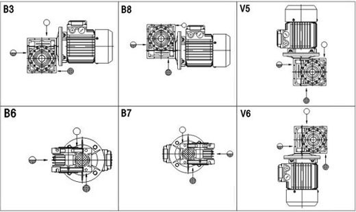
NMRV Mounting positions
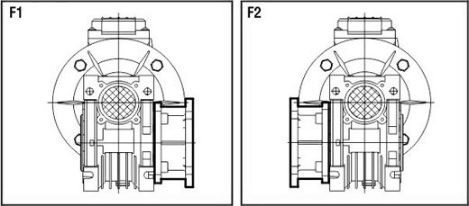
Output flange (F) configuration
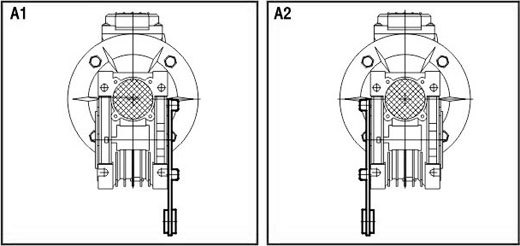
Torque arm (A) configuration
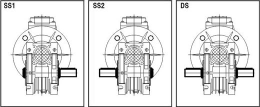
Worm gear output shaft (SS, DS) configuration
NMRV Size

NMRV 030 040 050 063 075 090 110 130 A 80 100 120 144 172 206 255 293 B 97 121.5 144 174 205 238 295 335 C 54 70 80 100 120 140 170 200 C1 44 60 70 85 90 100 115 120 D(H7) 14 18(19) 25(24) 25(28) 28(35) 35(38) 42 45 E(h8) 55 60 70 80 95 110 130 180 F 32 43 49 67 72 74 - - G 56 71 85 103 112 130 144 155 H 65 75 85 95 115 130 165 215 H1 29 36.5 43.5 53 57 67 74 81 I 55 70 80 95 112.5 129.5 160 179 L1 63 78 92 112 120 140 155 170 M 40 50 60 72 86 103 127.5 146.5 N 57 71.5 84 102 119 135 167.5 187.5 O 30 40 50 63 75 90 110 130 P 75 87 100 110 140 160 200 250 Q 44 55 64 80 93 102 125 140 R 6.5 6.5 8.5 8.5 11 13 14 16 S 21 26 30 36 40 45 50 60 T 5.5 6.5 7 8 10 11 14 15 V 27 35 40 50 60 70 85 100 PE M6*11(n=4) M6*8(n=4) M8*10(n=4) M8*14(n=8) M8*14(n=8) M10*18(n=8) M10*18(n=8) M12*21(n=8) b 5 6 8 8 8(10) 10 12 14 t 16.3 20.8(21.8) 28.3(27.3) 28.3(31.3) 31.3(38.3) 38.3(41.3) 45.3 48.8 α 0° 45° 45° 45° 45° 45° 45° 45° Kg 1.2 2.3 3.8 6.2 9 13 42.5 59 Note: Weight (kg) excluding motor
NRV Size

NRV 030 040 050 063 075 090 110 130 A 80 100 120 144 172 206 255 293 B 97 121.5 144 174 205 238 295 335 C 54 70 80 100 120 140 170 200 C1 44 60 70 85 90 100 115 120 D(H7) 14 18(19) 25(24) 25(28) 28(35) 35(38) 42 45 D1(j6) 9 11 14 19 24 24 28 30 E(h8) 55 60 70 80 95 110 130 180 F 32 43 49 67 72 74 - - G 56 71 85 103 112 130 144 155 H 65 75 85 95 115 130 165 215 H1 29 36.5 43.5 53 57 67 74 81 J 51 60 74 90 105 125 142 162 K 20 23 30 40 50 50 60 80 L1 63 78 92 112 120 140 155 170 M 40 50 60 72 86 103 127.5 146.5 N 57 71.5 84 102 119 135 167.5 187.5 O 30 40 50 63 75 90 110 130 P 75 87 100 110 140 160 200 250 Q 44 55 64 80 93 102 125 140 R 6.5 6.5 8.5 8.5 11 13 14 16 S 21 26 30 36 40 45 50 60 T 5.5 6.5 7 8 10 11 14 15 V 27 35 40 50 60 70 85 100 PE M6*11(n=4) M6*8(n=4) M8*10(n=4) M8*14(n=8) M8*14(n=8) M10*18(n=8) M10*18(n=8) M12*21(n=8) b 5 6 8 8 8(10) 10 12 14 t 16.3 20.8(21.8) 28.3(27.3) 28.3(31.3) 31.3(38.3) 38.3(41.3) 45.3 48.8 t1 10.2 12.5 16.0 21.5 27.0 27.0 31.0 33.0 m - - M6 M6 M8 M8 M10 M10 α 0° 45° 45° 45° 45° 45° 45° 45° Kg 1.2 2.3 3.8 6.2 9 13 42.5 59 Note: Weight (kg) excluding motor
Output flange Dimensions
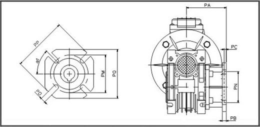
030 040 050 063 075 090 110 130 FA PA 54.5 67 90 82 111 111 139 152 PB 6 7 9 10 13 13 15 15 PC 4 4 5 6 6 6 6 6 PN 50 60 70 115 130 152 170 180 PM 68 75 85 150 165 175 230 255 PO 6.5(n=4) 9(n=4) 11(n=4) 11(n=4) 14(n=4) 14(n=4) 14(n=8) 16(n=8) PP 80 110 125 180 200 210 280 320 PQ 70 95 110 142 170 200 260 290 α1 45° 45° 45° 45° 45° 45° 45° 45° FB PA - 97 120 112 - 122 - - PB - 7 9 10 - 18 - - PC - 4 5 6 - 6 - - PN - 60 70 115 - 180 - - PM - 75 85 150 - 215 - - PO - 9(n=4) 11(n=4) 11(n=4) - 14(n=4) - - PP - 110 125 180 - 250 - - PQ - 95 110 142 - - - - α1 - 45° 45° 45° - 45° - - FC PA - 80 89 98 - 110 - - PB - 9 10 10 - 17 - - PC - 5 5 5 - 6 - - PN - 95 110 130 - 130 - - PM - 115 130 165 - 165 - - PO - 9.5(n=4) 9.5(n=4) 11(n=4) - 11(n=4) - - PP - 140 160 200 - 200 - - α1 - 45° 45° 45° - 45° - - FD PA - 58 72 107 - 151 - - PB - 12 14.5 10 - 13 - - PC - 5 5 5 - 6 - - PN - 80 95 130 - 152 - - PM - 100 115 165 - 175 - - PO - 9(n=4) 11(n=4) 11(n=4) - 14(n=4) - - PP - 120 140 200 - 210 - - α1 - 45° 45° 45° - 45° - - FE PA - - - 80.5 - - - - PB - - - 16.5 - - - - PC - - - 5 - - - - PN - - - 110 - - - - PM - - - 130 - - - - PO - - - 11(n=4) - - - - PP - - - 160 - - - - α1 - - - 45° - - - - Extension worm shaft (E) Dimensions

J d(j6) K m b1 t1 030 45 9 20 - 3 10.2 040 53 11 23 - 4 12.5 050 64 14 30 M6 5 16 063 75 19 40 M6 6 21.5 075 90 24 50 M8 8 27 090 108 24 50 M8 8 27 110 135 28 60 M10 8 31 130 155 30 80 M10 8 33 Worm gear output shaft (SS, DS) Dimensions
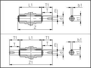
d(h6) T T1 L1 Z Z1 m b1 t1 030 14 30 32.5 63 102 128 M6 5 16 040 18 40 43 78 128 164 M6 6 20.5 050 25 50 53.5 92 153 199 M10 8 28 063 25 50 53.5 112 173 219 M10 8 28 075 28 60 63.5 120 192 247 M10 8 31 090 35 80 84.5 140 234 309 M12 10 38 110 42 80 84.5 155 249 324 M16 12 45 130 45 80 85 170 265 340 M16 14 48.5 Torque arm (A) Dimensions
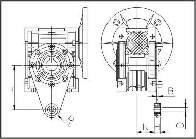
L H K D R B 030 85 14 24 8 15 4 040 100 14 31.5 10 18 4 050 100 14 38.5 10 18 4 063 150 14 49 10 18 6 075 200 25 47.5 20 30 6 090 200 25 57.5 20 30 6 110 250 30 62 25 35 6 130 250 30 69 25 35 6 -
Application:
RV Series apply to food, cooking machinery, printing machinery, carpentry machinery, small textile machinery, rubber machinery, small chemical machinery and plastic machinery.
Features:
RV series reducer is new-generation of products developed by our factory on the base of introducing foreign advanced technology, its main features are as follows:
1. Made of high-quality aluminium alloy, light weight and non-rusting.
2. Large output torque.
3. Smooth running and low noise.
4. High radiating efficiency.
5. Good-looking appearance, durable service life and small volume.
6. Suitable for omnibearing installation.
What Else Might You Learn?

Can't find the service you're looking for? Contact us!
To inquire about our products, please leave your email to us and we will contact you within 24 hours.
Contact Info
ADD
Donglou Industrial Area, Binhai,
Wenling, Zhejiang, China
TEL